Join to our channels: new products, coupons, best deals:
Flight controllers
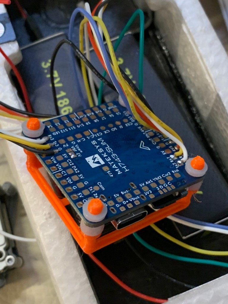
Matek H743-SLIM
Multirotors → Racing FPV-Hubschrauber → Flight controllers → H7 FCs → Matek H743-SLIM
| MCU: | H743 |
| : | ICM20602 & MPU6000 |
| : | DPS310 |
| OSD: | + |
| CAM in: | 2 |
| : | 2-8S |
| 3.3V BEC: | 0.2A |
| 5V BEC: | 2A |
| : | - |
| PWM: | 13 |
| : | - |
| ESC: | - |
| BLHeli: | - |
| Empfänger: | - |
| RSSI: | + |
| VTX: | - |
| : | 7 |
| : | 7 |
| I2C: | 2 |
| CAN: | 1 |
| : | + |
| : | + |
| Vbat: | 2 |
| CURR pad: | 2 |
| Air speed: | + |
| IR/INR pad: | + |
| Blackbox: | MicroSD |
| : | Type-C |
| USB pads: | + |
| : | + |
| Bluetooth: | - |
| : | 36x36x5mm |
| : | 30.5x30.5mm |
| Gewicht: | 7g |
Flight Controller H743-SLIM
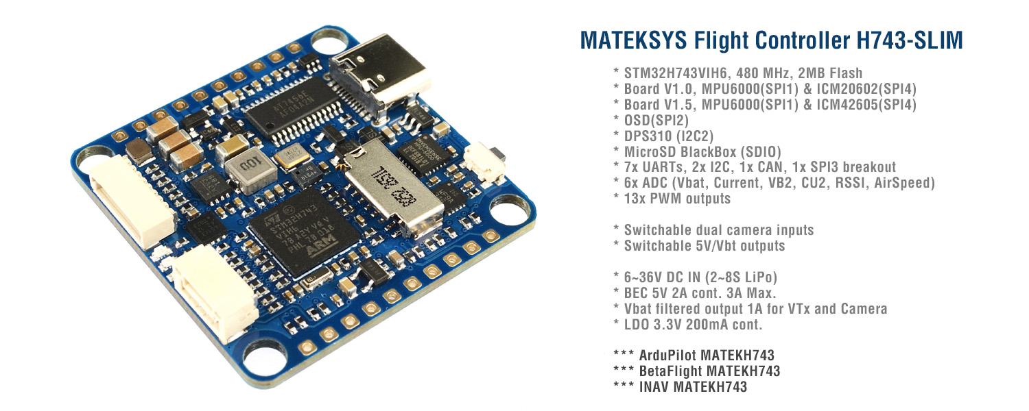
STM32H743VI, ICM20602 & MPU6000, DPS310, OSD, 7x UARTs, 2x I2C, 1xCAN, 13x PWM outputs, BEC5V,
Gallery
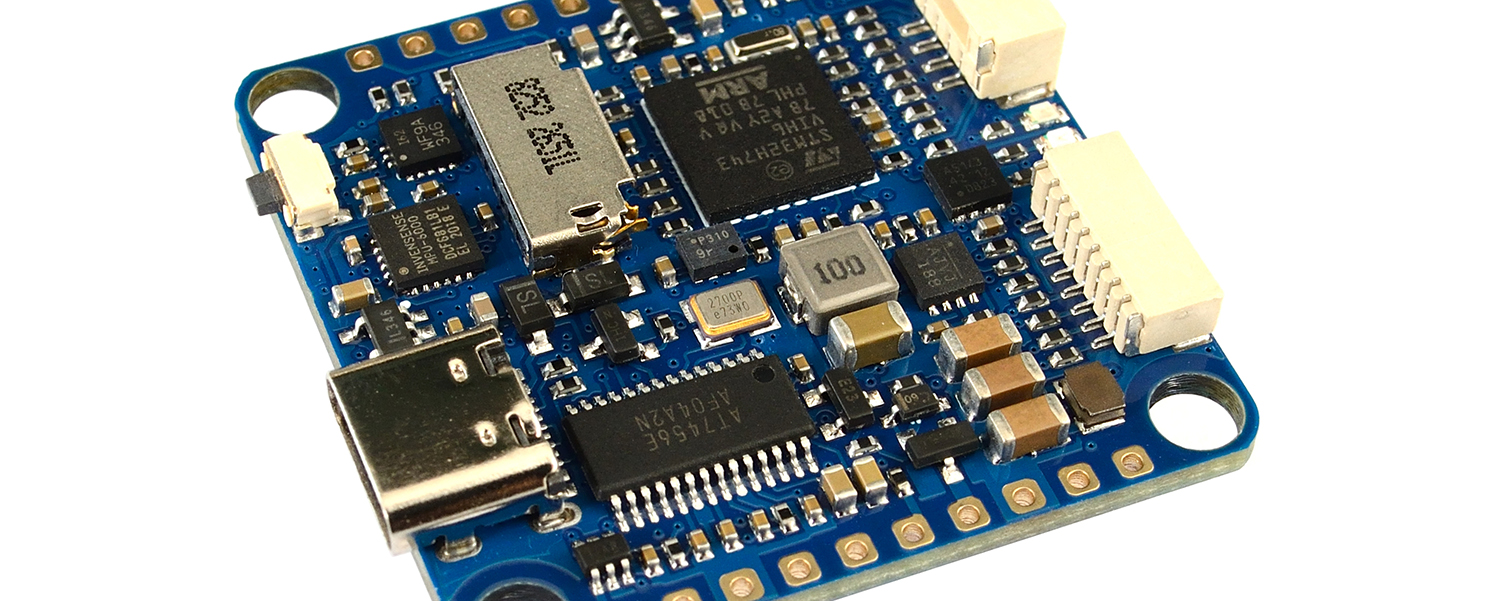
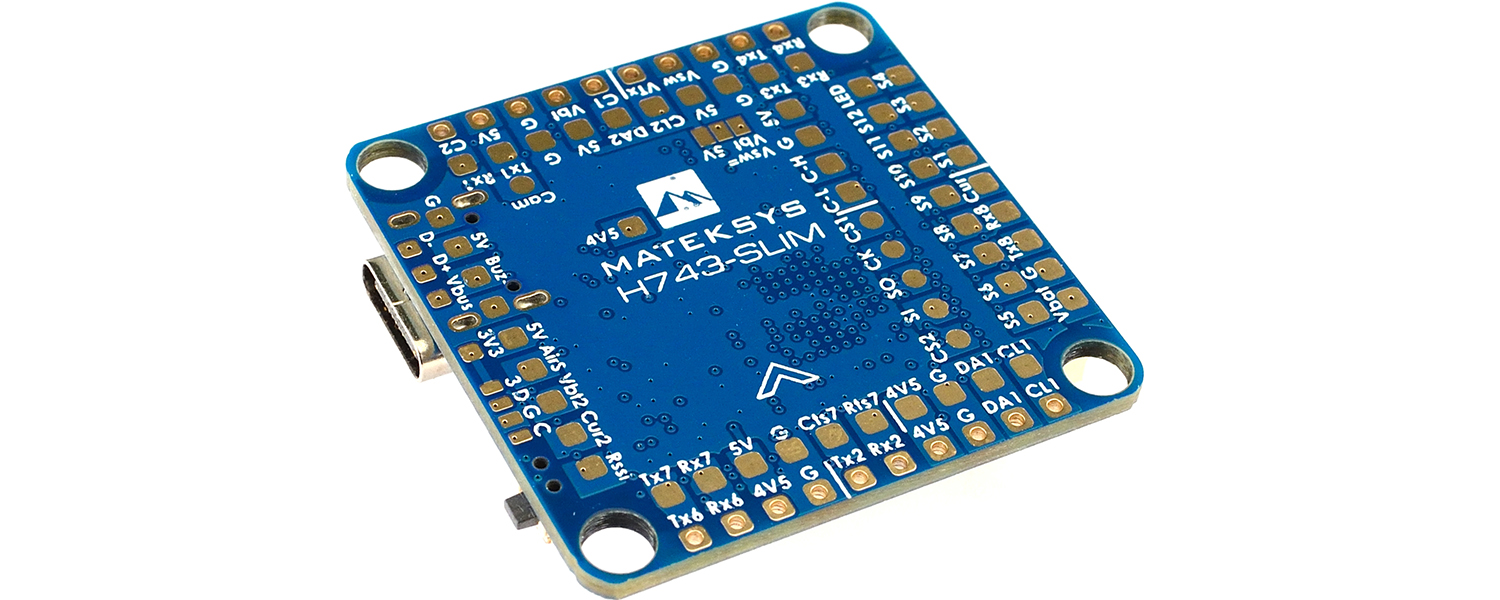
Specifications
FC Specifications
- MCU: STM32H743VIH6, 480MHz , 1MB RAM, 2MB Flash
- IMU: MPU6000 (SPI1) & ICM20602 (SPI4)
- Baro: Infineon DPS310 (I2C2)
- OSD: AT7456E (SPI2)
- Blackbox: MicroSD card socket (SDIO)
- 7x Uarts (1,2,3,4,6,7,8) with built-in inversion.
- 13x PWM outputs(including “LED” pad)
- 2x I2C
- 1x CAN
- 6x ADC (VBAT, Current, RSSI, Analog AirSpeed, Vbat2, Cur2)
- 3x LEDs for FC STATUS (Blue, Red) and 3.3V indicator(Red)
- 1x SPI3 breakout
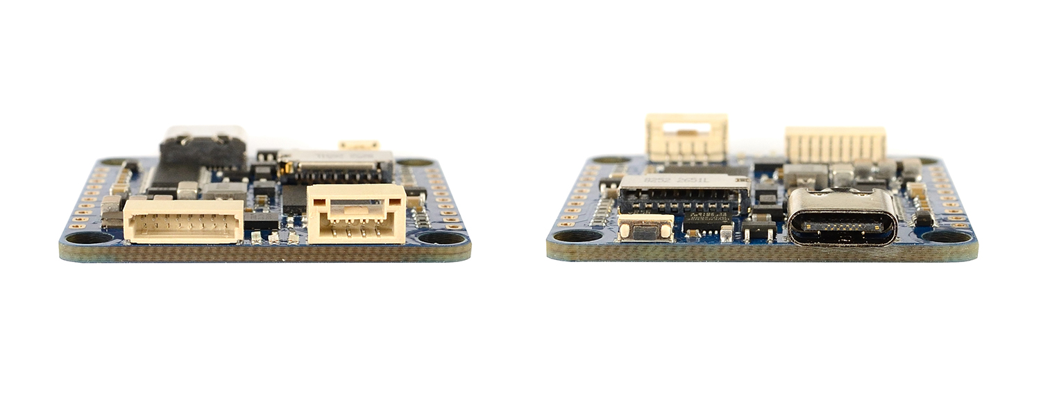
- USB Type-C(USB2.0)
- 1x JST-SH1.0_8pin connector (Vbat/G/Curr/Rx8/S1/S2/S3/S4)
- 1x JST-GH1.25_4pin connector (5V/CAN-H/CAN-L/G)
- Dual Camera Inputs switch
- 5V/Vbat filtered power ON/OFF switch
- DJI FPV OSD is supported by any spare UART
Power
- Vbat Input: 6~36V (2~8S LiPo)
- BEC: 5V 2A cont. (Max.3A)
- LDO 3.3V: Max.200mA
- No Current Sensor built-in
- ADC Vbat2 pad supports Max. 69V (voltage divider: 1K:20K)
- Static power: 200mA@5V with Betaflight, 150mA@5V with ArduPilot
FC Firmware
- ArduPilot(ChiBiOS): MATEKH743
- BetaFlight: MATEKH743
- INAV: MATEKH743 (To be supported soon)
Physical
- Mounting: 30.5 x 30.5mm, Φ4mm with Grommets Φ3mm
- Dimensions: 36 x 36 x 5 mm
- Weight: 7g
Including
- 1x H743-SLIM
- 6x Silicon grommets M4 to M3
- 1x JST-SH1.0_8pin cable, 5cm
- 2x JST-SH1.0_8pin connectors
- 1x JST-GH-4P to JST-GH-4P cable for CAN port, 20cm
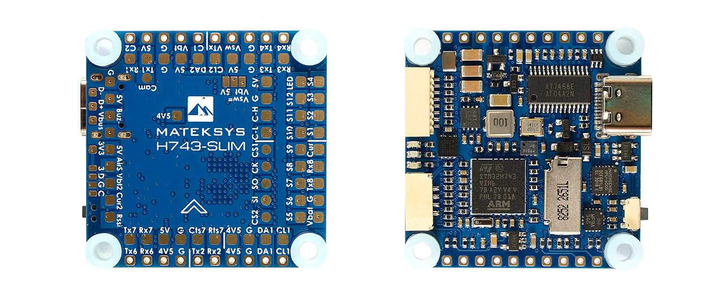
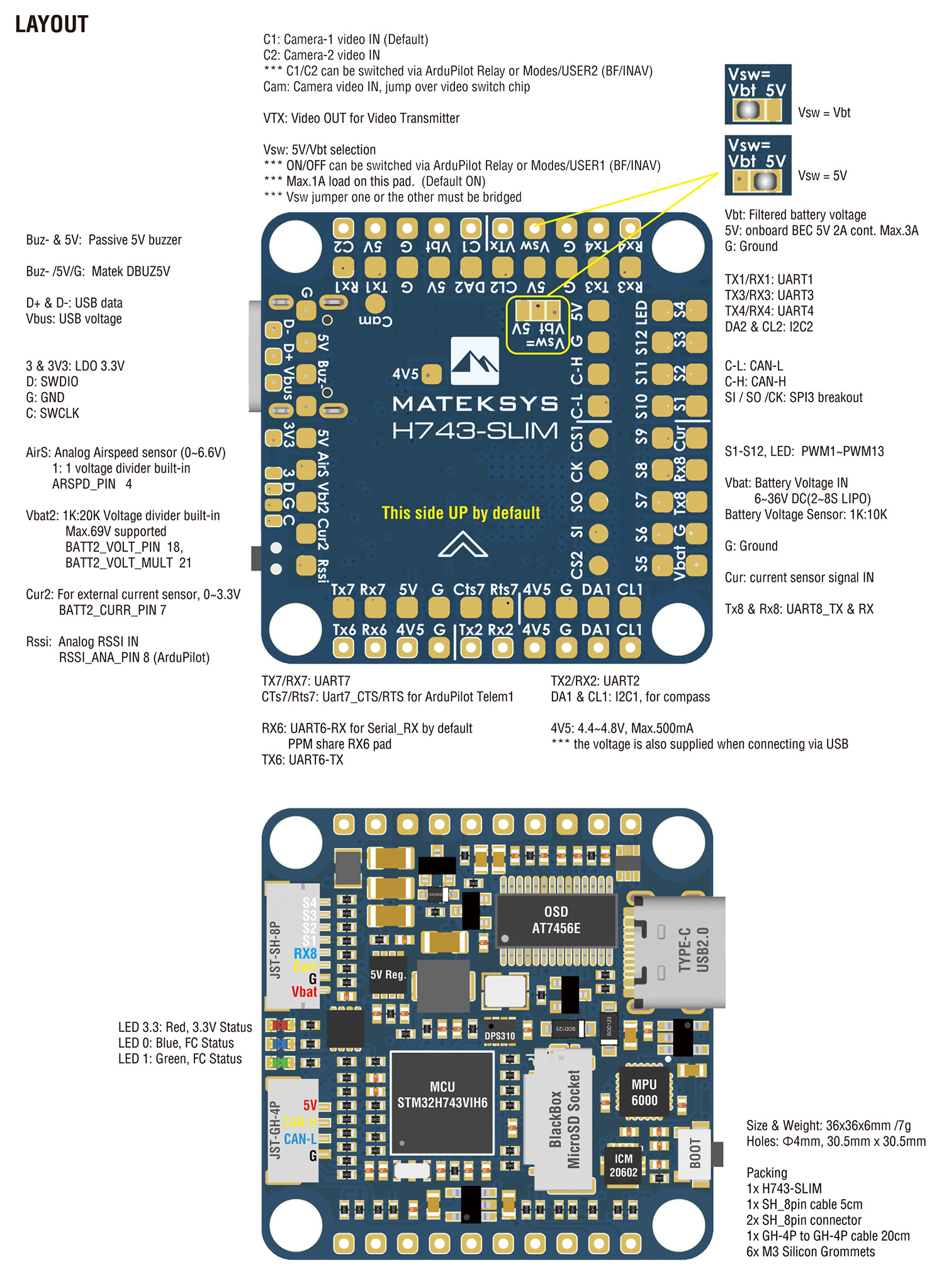
Layout
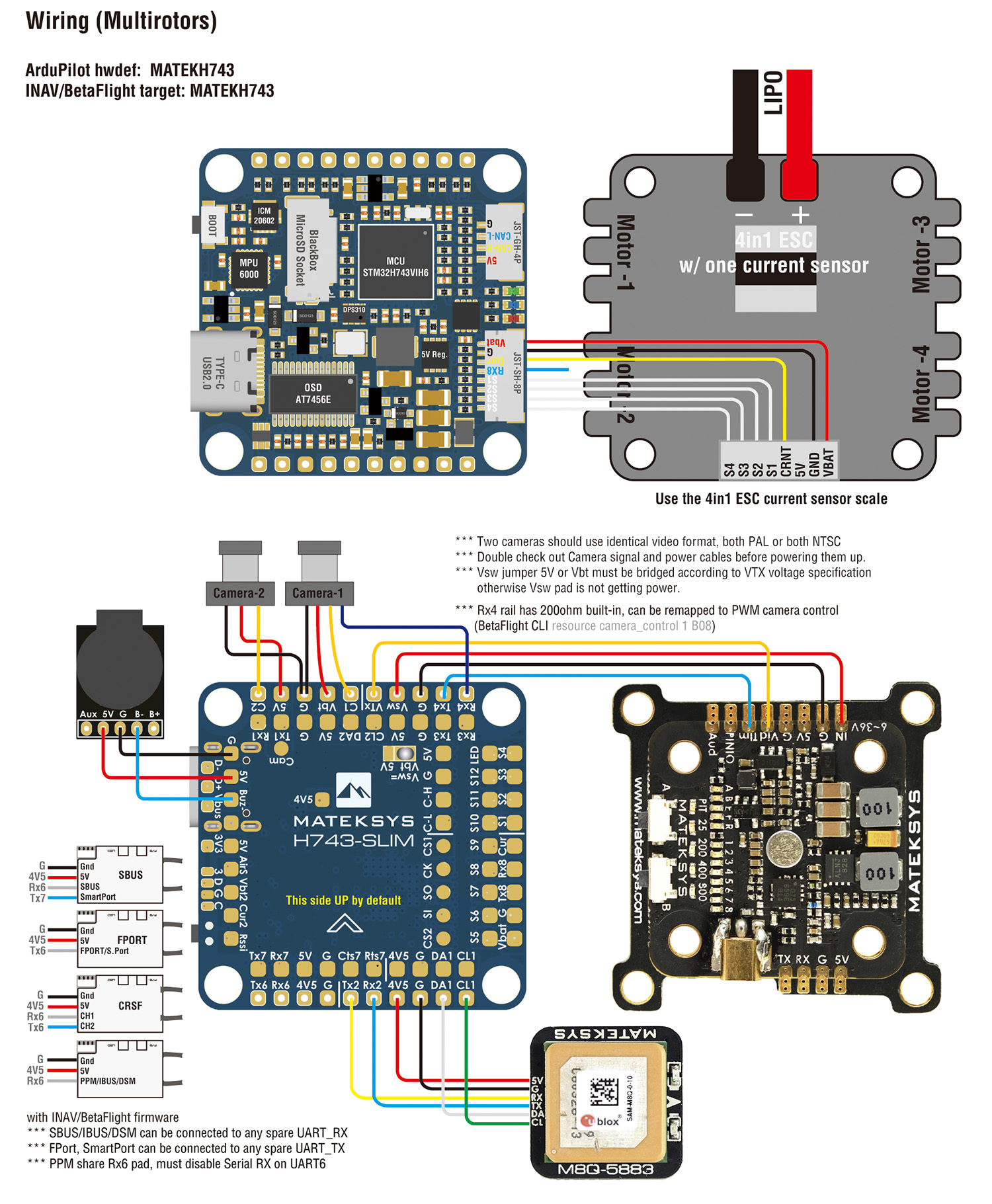
Wiring
ArduPilot mapping
| PWM PWM1~PWM13 are Dshot and PWM capable. However, mixing Dshot and normal PWM operation for outputs is restricted into groups, ie. enabling Dshot for an output in a group requires that ALL outputs in that group be configured and used as Dshot, rather than PWM outputs. If servo and motor are mixed in same group, make sure this group run lowest PWM frequency according to the servo specification. ie. Servo supports Max. 50Hz, ESC must run at 50Hz in this group. | S1 | PB0 | 5 V tolerant I/O | PWM1 GPIO50 | TIM8_CH2N | Group1 |
| S2 | PB1 | 3.3 V tolerant I/O | PWM2 GPIO51 | TIM8_CH3N | ||
| S3 | PA0 | 5 V tolerant I/O | PWM3 GPIO52 | TIM5_CH1 | Group2 | |
| S4 | PA1 | 5 V tolerant I/O | PWM4 GPIO53 | TIM5_CH2 | ||
| S5 | PA2 | 5 V tolerant I/O | PWM5 GPIO54 | TIM5_CH3 | ||
| S6 | PA3 | 5 V tolerant I/O | PWM6 GPIO55 | TIM5_CH4 | ||
| S7 | PD12 | 5 V tolerant I/O | PWM7 GPIO56 | TIM4_CH1 | Gourp3 | |
| S8 | PD13 | 5 V tolerant I/O | PWM8 GPIO57 | TIM4_CH2 | ||
| S9 | PD14 | 5 V tolerant I/O | PWM9 GPIO58 | TIM4_CH3 | ||
| S10 | PD15 | 5 V tolerant I/O | PWM10 GPIO59 | TIM4_CH4 | ||
| S11 | PE5 | 5 V tolerant I/O | PWM11 GPIO60 | TIM15_CH1 | Group4 | |
| S12 | PE6 | 5 V tolerant I/O | PWM12 GPIO61 | TIM15_CH2 | ||
| LED | PA8 | 5 V tolerant I/O | PWM13 GPIO62 | TIM1_CH1 | Group5 | |
| SERVO13_FUNCTION 120, NTF_LED_TYPES neopixel | ||||||
| ADC | No pad 1K:10K divider builtin | PC0 | 0~36V | on board battery voltage | BATT_VOLT_PIN BATT_VOLT_MULT | 10 11.0 |
| No pad | PC1 | 0~3.3V | on board current sensor | BATT_CURR_PIN BATT_AMP_PERVLT | 11 40 | |
| Vbat2 Pad 1K:20K divider builtin | PA4 | 0~69V | Vbat2 ADC | BATT2_VOLT_PIN BATT2_VOLT_MULT | 18 21.0 | |
| Cur2 Pad | PA7 | 0~3.3V | Cur2 ADC | BATT2_CURR_PIN BATT2_AMP_PERVLT | 7 / | |
| RSSI Pad | PC5 | 0~3.3V | RSSI ADC Analog RSSI | RSSI_ANA_PIN RSSI_TYPE | 8 1 | |
| AirS Pad 10K:10K divider builtin | PC4 | 0~6.6V | AirS ADC Analog Airspeed | ARSPD_PIN ARSPD_TYPE | 4 2 | |
| I2C | I2C1 CL1/DA1 | PB6/PB7 | 5 V tolerant I/O | Digital Airspeed I2C | ARSPD_BUS | 1 |
| MS4525 MS5525 DLVR-L10D | ARSPD_TYPE | 1 3 9 | ||||
| Compass | COMPASS_AUTODEC | 1 | ||||
| I2C2 CL2/DA2 | PB10/PB11 | 5 V tolerant I/O | on board Baro DPS310 | |||
| CAN | CAN1 | PD0/PD1 | 5 V tolerant I/O | F103/F303 CAN Node | CAN_D1_PROTOCOL CAN_P1_DRIVER | 1 1 |
| CAN GPS | GPS_TYPE | 9 | ||||
| CAN Compass | COMPASS_TYPEMASK | 0 | ||||
| CAN Airspeed sensor | ARSPD_TYPE | 8 | ||||
| UART | USB | PA11/PA12 | 5 V tolerant I/O | USB | console | SERIAL0 |
| RX7 TX7 RTS7 CTS7 | PE7/8/9/10 | 3.3 V tolerant I/O | UART7 | telem1 | SERIAL1 | |
| TX1 RX1 | PA9/PA10 | 5 V tolerant I/O | USART1 | telem2 | SERIAL2 | |
| TX2 RX2 | PD5/PD6 | 5 V tolerant I/O | USART2 | GPS1 | SERIAL3 | |
| TX3 RX3 | PD8/PD9 | 5 V tolerant I/O | USART3 | GPS2 | SERIAL4 | |
| TX8 RX8 | PE1/PE0 | 5 V tolerant I/O | UART8 | USER | SERIAL5 | |
| TX4 RX4 | PB9/PB8 | 5 V tolerant I/O | UART4 | USER | SERIAL6 | |
| TX6 RX6 | PC6/PC7 | 5 V tolerant I/O | USART6 | RC input/Receiver | SERIAL7 | |
| RX6 | SBUS/IBUS/DSM | |||||
| RX6 | PPM | |||||
ArduPilot Relay
- Camera-1 and Vsw On by default
- Make sure 2 cameras are set with identical video format, both PAL or both NTSC.
# GPIOs
- PD10 PINIO1 OUTPUT GPIO(81) //Vsw pad power switch
- PD11 PINIO2 OUTPUT GPIO(82) //Camera switch
# RCx_OPTION: RC input option
- 28 Relay On/Off
- 34 Relay2 On/Off
- 35 Relay3 On/Off
- 36 Relay4 On/Off
e.g.
- RELAY_PIN 81 //Vsw GPIO
- RC7_OPTION 28 //Relay On/Off, Use CH7 of Transmitter to switch Vsw
- RELAY_PIN2 82 //Camera switch GPIO
- RC8_OPTION 34 //Relay2 On/Off, Use CH8 of Transmitter to switch camera
or
- RELAY_PIN3 81 //Vsw GPIO
- RC9_OPTION 35 //Relay3 On/Off, Use CH9 of Transmitter to switch Vsw
- RELAY_PIN4 82 //Camera switch GPIO
- RC10_OPTION 36 //Relay4 On/Off, Use CH10 of Transmitter to switch camera
The configured feature will be triggered when the auxiliary switch’s pwm value becomes higher than 1800. It will be deactivated when the value falls below 1200.
Check the pwm value sent from the transmitter when the switch is high and low using the Mission Planner’s Initial Setup >> Mandatory Hardware >> Radio Calibration screen. If it does not climb higher than 1800 or lower than 1200, it is best to adjust the servo end points in the transmitter.
reserved
reserved
Tips
- ArduPilot Firmware
- INAV is expected to support H743 in 2.6.
- H743-SLIM has betaflight firmware preloaded for QC
- BetaFlight target is not on the Github, pls download BetaFlight firmware from our website.
- If you flash ArduPilot firmware via BetaFlight configurator. there is a known issue that flash process will freeze at 50% if “full chip erase” is selected. Disable full chip erase when flashing, then reset to default in Mission Planner after flashing.
- It is highly recommended to use STM32CubeProgrammer to erase MCU and upload firmware http://www.mateksys.com/?p=6905
Resellers
- MSRP: USD55.99
- ETA: End Oct.
Share
Preise für Matek H743-SLIM in den Läden
Angebote gefunden: 32 (Banggood1)
| Store | Stock level | Lot price | Shipping cost | Coupon / promocode | Pcs./lot | 1pc price |
| Banggood | Out of stock | $80 | 1 | $80 |
Siehe auch

Mateksys CANPDB-4A BEC & JST-GH Splitter
$17
Matek H743-SLIM - super light support for Dart250g

